One of the things I’ve been watching throughout the Pandemic is Adam Savage’s ‘Tested’ YouTube Channel, particularly the tool tips and one day builds. I enjoy the idea of making stuff, being able to bash together some solution to a problem or make an idea into a real thing. I enjoy the idea of that. The reality hasn’t been realized, quite.
Still, I can on occasion make myself useful.
For Father’s Day, I got an anemometer for my Netatmo setup. I got the rest of the Netatmo suite for Christmas this past year, and I’ve been enjoying being able to see what’s going on, environmentally. If you’re unfamiliar, the base set comes with an indoor module that connects to wifi and plugs into the wall. It measures temperature, humidity, pressure, noise level and CO2. Then there’s an outdoor module that communicates with the indoor one and runs on batteries. It measures temperature and humidity. I also got a rain gauge at the same time.
As you might imagine, where you place the rain gauge and anemometer is pretty important. Up to now, my rain gauge has lived on a side table on the patio. An OK spot, but it did get knocked/blown/etc. off the table at least once. I had to put a few pieces back together, and I’m not sure it’s worked incredibly precisely since. It does pick up rain, I’m just not sure it’s as sensitive as it used to be.
Anyhow, particularly with the anemometer, which has to be pointed a specific direction, I figured it would be a good idea to mount these things somewhere more suitable. Importantly, they both have a standard “tripod mount” socket on the bottom (1/4″-20 screw).
Netatmo does sell mounts for the instruments, but they’re relatively expensive and I’d have to wait for them to arrive. I briefly considered mounts for outdoor security cameras, but these too are not inexpensive. Money aside though, I’d decided the best place for these was mounted to the top of my kids’ playset. And I wanted to try to avoid permanently attaching them.
Then I hit on the idea of using a PVC pipe with a cap, drilling a hole through the cap and then poking the screw up through the cap, holding it in place with a nut and washer. With that setup — essentially a PVC pipe with the instrument stuck on the end of it — I could even raise the anemometer up above the height of the playset.
With the design of the mount itself figured out, I then had to work out how to attach these to the playset. I complicated things for myself by planning to attach the anemometer to the aforementioned upright — a vertical post. But I wanted to put the rain gauge on the end of the crossbar holding all the swings and such, to give it as much clearance from any rain-blocking obstacles. And again, I wanted to do this without screwing into the playset itself.
One thing that popped into my head was “those things that are like long metal strips with holes and a screw contraption, and you slip the end under the screw, turn the screw and it tightens like a slip knot”. Unfortunately that’s not a thing that googles easily. Took me a while to figure out those are called “hose clamps”. I thought I’d cut some slots in the PVC, run the hose clamp through the PVC, around the post/crossbar and tighten it down.
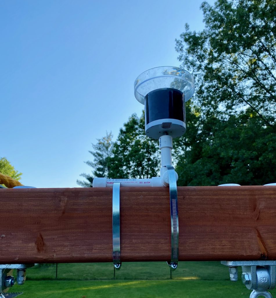
So, the plan: The anemometer would be perched at the top of a vertical PVC pipe, cut a couple sets of vertical slots and use two hose clamps to attach. The rain gauge is slightly more difficult. I was figuring on small diameter PVC, and I didn’t know if trying to stand it up on top of the crossbar beam would work. So I thought maybe perch the rain gauge on a short pipe, then go into a tee or elbow with short lengths for a little more stability on the base. Buying the parts, I settled on a three-way elbow (think the three edges coming out of the corner of a cube).
Another wrinkle in buying the parts, turns out hose clamps are made for hoses. Which are generally smaller than the beams making up play equipment. For some reason I assumed those things I was imagining weren’t specific to hoses and would be made in any number of lengths, like zip-ties or something. Why aren’t they? I checked the store app and saw sometimes these are used on flagpoles, so I stopped by that area, which turned out to be a red herring. After another lap of the store I managed to stumble on the HVAC aisle, realizing that sometimes ducts are also made up of hose-type structures and are generally larger than residential-use water hoses. Bingo. They had clamps labeled 4-inch and 6-inch. I assumed this is diameter of the hose it’s meant to clamp. The upright was about 3.5″ square (total distance 14 inches, plus allowance for going through the PVC on one side) and the crossbar was 5″ tall and 3.5″ wide (total distance 17 inches, plus allowance). I don’t know anything about how the clamps are measured, but I do know the circumference of a 4-inch diameter circle is only a little more than 12 inches and a 6-inch diameter circle has a circumference of a little more than 18 inches. So I figured the 4-inch ones were too small for both and the 6-inch ones would be just large enough for the crossbar.
So, I bought four of the 6-inch clamps. And then upon returning home I discovered that they’re not built so you can tighten them down to nothing. The 6-inch ones were far too large for the upright — I wouldn’t be able to tighten them enough to hold the PVC to it. But they were more than large enough for the crossbar, so I thought the 4-inch clamps might work for the upright. My second trip of the day to the home improvement store ensued.
Final equipment list:
- 1/2″ x 2′ PVC pipe (2)
- 1/2″ PVC el with side outlet (1)
- 1/2″ PVC slip cap (4)
- 6″ Adjustable Metal Worm Drive Clamp (2)
- 4″ Adjustable Metal Worm Drive Clamp (2)
- 1/4″ x 1″ Stainless Machine Screw (2)
- 1/4″ Stainless Flat Washer (2)
- 1/4″ Stainless Hex Nut (2)
Total material cost before tax, $16.53. The single most expensive component was the PVC el fitting at $2.15 (I briefly considered making some structure that would support the rain gauge and anemometer on the same PVC structure, but those fittings really eat into the cost).
Now that all the equipment was squared away, making could commence. I drilled 1/4″ holes in two caps, and put a washer on each screw, then slipped it through the underside of the cap, tightening a nut down on top of it. Probably could’ve gone with 3/4″ or even 1/2″ screws.
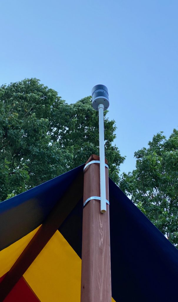
The anemometer tube was simplest. I used a cutting wheel on a Dremel to cut a slot in opposite sides of the pipe a few inches from one end. I then made another set of slots just below the halfway point of the pipe. I slipped the hose clamps through the slots, popped the cap on top and done.
The rain gauge tube was slightly more complicated. I put the PVC in the el fitting and cut off a couple inches above the fitting. This would be where the rain gauge sits. Next I cut off a very small length of pipe — just a couple inches. This would run perpendicular to the direction of the crossbar (and parallel with the direction of the hose clamp). Finally I cut a longer length of pipe, maybe four or five inches, to run parallel with the crossbar and serve as another attachment point for a clamp. I cut a slot in this longer pipe for a clamp, and a slot in the first pipe just above where it fit in the el for the other clamp.
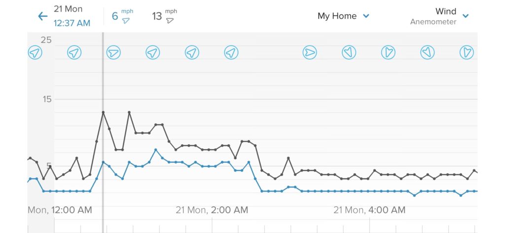
Took everything out to the playset, tightened it down, attached the instruments to the caps, then put the caps on their pipes and everything seems to be working OK. I did need to calibrate the height of the wind gauge in the Netatmo software, but other than that, everything seems to be working OK. We even had a big storm early the next morning and although the wind overturned some patio furniture, the anemometer registered it and was still standing the next morning.

So, that’s how I made a couple mounts for my Netatmo devices for less than $20. Might take them down and spray paint the PVC or something. But overall I’m pretty happy with this hour-or-so project that solved a problem.
